Preparation of Signal Phase and Timing (SPaT) data#
Section author: Zachary Jerome <zjerome@umich.edu>
Signal Phase and Timing (SPaT) data is provided by the governing transportation
agency in the form of signal work orders. These work orders must be converted to
a compatible form before they can be loaded by the MTLDP. The current compatible
format consists of a collection of seven csv files stored in the raw_spat
directory. This tutorial describes the required information in each csv file.
The tutorial is facilitated by an example work order for a made up intersection
(Michigan Ave. and Wolverine St.).

Step 1: Network Mapping CSV#
The network_mapping_data.csv file matches the SPaT data to the MTLDP map
network. Each signal work order is for a specific controller which may operate
several intersections, so they must be matched to each intersection they control
using their respective node ids in the map network. In addition, each phase
configured in the controller may operate several intersection movements and
overlaps. The intersection movements are numbered according to the following
figure:

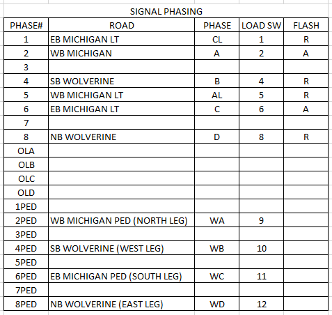
The work order usually contains the required information for this csv file in the “Signal Phasing” section:
The following table demonstrates how information from this intersection is
inputted into the network_mapping_data.csv file. The “node_id” is the
designated id for this intersection in the MTLDP map network, while the
“controller_id” is the id designated from the signal work order. There is a row
for each configured phase in the controller, denoted by the “Phase#” in the
signal work order.
The movements controlled by each phase are put under the “movement_indices” channel with each movement split by the “|” character. For example, “NB Wolverine” controls the right, left, and straight movements, which are movements 7, 4, and 10 from the “Intersection Movement Indices” figure from above. Overlaps are also controlled by a phase, which will be reported in the overlap standards in the work order. The “flashing” channel is taken directly from the work order.
node_id |
controller_id |
phase |
movement_indices |
flashing |
|---|---|---|---|---|
10234145 |
742 |
1 |
1 |
R |
10234145 |
742 |
2 |
2|9 |
A |
10234145 |
742 |
4 |
3|8|12 |
R |
10234145 |
742 |
5 |
5 |
R |
10234145 |
742 |
6 |
6|11 |
A |
10234145 |
742 |
8 |
4|7|10 |
R |
Step 2: Ring Structure CSV#
The ring_structure_data.csv file provides information about the ring
configuration and basic signal timings. The work order usually contains
the required information for this csv file in the “Ring Structure” and
“Basic Timings” sections.
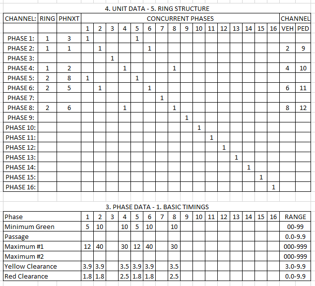
Below is a table showing how this information is reported in the csv file.
There is a row for each configured phase in the controller. “Version” is a
user-defined term for the structure version. If there are multiple
configurations of the structure or if any of the terms change in future
retimings, another complete set of the structure configuration should be put in
this file with a different version number. Dates for each version are reported
in the version_history.csv file described below. The “ring”, “next_phase”,
and “ped_channel” channels are all taken directly from the work order.
“Concurrent_phases” provides all the possible phases that can occur at the same
time. If there are multiple, each phase is separated by the “|” character.
“Channel” is taken directly from the “veh” column in the work order. Yellow and
clearance timings are taken directly from the basic timings chart. Note that
the “min_green” channel IS NOT what is provided in the basic timings chart.
Check with your agency to verify their minimum green requirements based on
pedestrian timings. Any information not known should be marked with “-1”.
version |
controller_id |
phase |
ring |
next_phase |
concurrent_phases |
channel |
ped_channel |
min_green |
yellow |
clearance |
|---|---|---|---|---|---|---|---|---|---|---|
0 |
742 |
1 |
1 |
4 |
5 |
-1 |
-1 |
-1 |
3.9 |
1.8 |
0 |
742 |
2 |
1 |
1 |
6 |
2 |
9 |
-1 |
3.9 |
1.8 |
0 |
742 |
4 |
1 |
2 |
8 |
4 |
10 |
-1 |
3.5 |
2.5 |
0 |
742 |
5 |
2 |
8 |
1 |
-1 |
-1 |
-1 |
3.9 |
1.8 |
0 |
742 |
6 |
2 |
5 |
2 |
6 |
11 |
-1 |
3.9 |
1.8 |
0 |
742 |
8 |
2 |
6 |
4 |
8 |
12 |
-1 |
3.5 |
2.5 |
Step 3: Dial Split CSV#
The dial_split_data.csv file includes all the timing information for each
programed dial/split. The sample work order below includes information for one
dial.
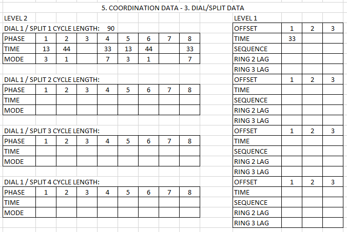
The “version” channel follows the same procedure as before. All the other channels shown in the example csv file below are taken directly from the work order. Here, we include dial/split “2:1” and “3:1”, which are not shown in the example work order.
version |
controller_id |
dial |
split |
1_time |
1_mode |
2_time |
2_mode |
3_time |
3_mode |
4_time |
4_mode |
5_time |
5_mode |
6_time |
6_mode |
7_time |
7_mode |
8_time |
8_mode |
cycle |
offset |
|---|---|---|---|---|---|---|---|---|---|---|---|---|---|---|---|---|---|---|---|---|---|
0 |
742 |
1 |
1 |
13 |
2 |
44 |
1 |
-1 |
-1 |
33 |
7 |
13 |
2 |
44 |
1 |
-1 |
-1 |
33 |
7 |
90 |
33 |
0 |
742 |
2 |
1 |
12 |
2 |
40 |
1 |
-1 |
-1 |
38 |
7 |
12 |
2 |
40 |
1 |
-1 |
-1 |
38 |
7 |
90 |
23 |
0 |
742 |
3 |
1 |
13 |
2 |
46 |
1 |
-1 |
-1 |
31 |
7 |
13 |
2 |
46 |
1 |
-1 |
-1 |
31 |
7 |
90 |
25 |
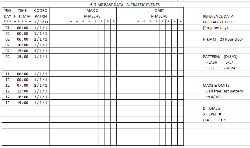
Step 4: TOD Event CSV#
Here we show the example work order and how you would input the time of day
(TOD) information into the tod_event_data.csv file. This file reports how
the dial/splits are assigned throughout the day.
version |
controller_id |
program_day |
start |
end |
dial |
split |
|---|---|---|---|---|---|---|
0 |
742 |
1 |
0 |
24 |
1 |
1 |
0 |
742 |
2 |
0 |
6 |
1 |
1 |
0 |
742 |
2 |
6 |
10 |
2 |
1 |
0 |
742 |
2 |
10 |
15 |
1 |
1 |
0 |
742 |
2 |
15 |
19 |
3 |
1 |
0 |
742 |
2 |
19 |
24 |
1 |
1 |
0 |
742 |
11 |
0 |
24 |
1 |
1 |
0 |
742 |
12 |
0 |
7 |
1 |
1 |
0 |
742 |
12 |
7 |
11 |
2 |
1 |
0 |
742 |
12 |
11 |
16 |
1 |
1 |
0 |
742 |
12 |
16 |
19 |
3 |
1 |
0 |
742 |
12 |
19 |
24 |
1 |
1 |
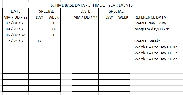
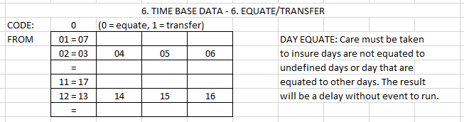
Step 5: Program Day CSV#
The program_day_data.csv file matches the program days reported in the TOD
event file to calendar dates. There are two types of program days: special
days and weekdays. In the time of year portion of the signal work order,
December 24th is designated as a special day with program day 12. This
information is reflected in the csv file. For the weekdays, the
equate/transfer portion of the signal work order reports that program
day 1 = 7, and 2 = 3, 4, 5, 6. In this particular work order, Sunday is 1, so this
tells us that all the weekend days have program day 1 and all the week days
have program day 2. You do not need to include the program day information for
program days greater than 10 for weekday information. The week number csv file
described below and processing code will cover that.
controller_id |
program_day |
date |
day_of_week |
|---|---|---|---|
742 |
12 |
12/24/2024 |
|
742 |
1 |
Saturday |
|
742 |
1 |
Sunday |
|
742 |
2 |
Monday |
|
742 |
2 |
Tuesday |
|
742 |
2 |
Wednesday |
|
742 |
2 |
Thursday |
|
742 |
2 |
Friday |
Step 6: Program Week CSV#
This simple file contains information about week program week numbers start in the calendar year. Refer to the time of year events section of the work order example above.
controller_id |
week_num |
start |
|---|---|---|
742 |
1 |
07/01/2023 |
742 |
0 |
08/23/2023 |
742 |
1 |
06/07/2024 |
Step 7: Version History CSV#
The version_history.csv file records the start dates for different
versions of the SPaT parameters. If you have SPaT history available, you
should document the changes here. This will allow the code to fetch the
correct information based on the dates of your analysis.
controller_id |
start_date |
dial_split |
ring_structure |
tod_events |
|---|---|---|---|---|
742 |
07/01/2023 |
0 |
0 |
0 |